This page is available in
English too.![]()
Battery Management System
(Projekt je završen 2015.
godine)
Litijske baterije moraju imati nadzorni sistem, koji će spriječiti oštećenje baterije, ako što će i poboljšati perfomanse baterijskog paketa te produžiti njegov životni vijek. In this BMS (battery management system) the cell module monitors the voltage of the cell and sends data to central unit whenever the cell voltage is over the limits (too high or to low) or when it is polled.
The cell modules are connected in daisy chain and the messages are transferred at speed of 9600bps. The first cell module in the battery has been mounted on the most positive cell.
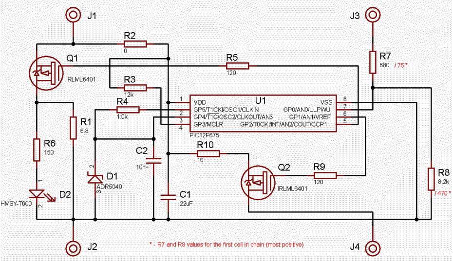
Here's electrical drawing of the cell module:

Transistor Q1 is used for bleeding the cell when
it reaches programmable threshold point. Resistor R1 has to be chosen according
to the nominal cell voltage and allowed power dissipation; recommended value is
8.2 Ohms for LiFePO4 cells and 10 Ohms for LiPo cells. Large cells need bigger
bleeding current and this cell module can bleed current up to 1A (with R1
resistor on the heat sink).
The diode D1 with resistor R6 can be omitted as is used only to indicate
bleeding process, which can be indicated on central module too.
Major advantage of this cell module is very low
current consumption in standby mode. When it is not polled, the module draws max
6ľA from LiPo cell, which can be
even less than 3ľA on LiFePO4 cell.
The low power consumption has been achieved by putting the microcontroller in
sleep mode, leaving running only watchdog timer and enabling interrupt on pin
GP0 (command input). In idle mode the microcontroller has been waked up every
~2.3 second when it measures the voltage and sends data out if voltage of the
cell is out of limits (Hi/Lo alarm).
Of course, the microcontroller has been waked up when any data comes in through
GP0 port too.
The voltage of the cell has been measured in such way that the reference voltage of the A/D converter is the cell and the voltage of the reference voltage has been converted through 10bit A/D input. The cell module sends (when is polled) the digitized value of the reference voltage, which is reciprocal to cell voltage. The central unit has to calculate the cell voltage from this value. The formula is:
Ucell = Uref * 1024 / ADref
Where ADref is digitized
reference voltage.
The calibration constant is Uref*1024 and it is stored in nonvolatile
microcontroller's memory as well as other three values: High Alarm voltage, Low
Alarm voltage and Bleeding Threshold voltage. These parameters of the cell
module can be easily changed with appropriate commands send to the module.
The central module (when
it is initialized) has to read calibration voltages for all cells in the chain
in order to calculate cell voltages. It is advisable to store the cell
calibration constants in the central module in order to reduce the communication
with the cells.
The central module doesn't need these constants if it has no display, i.e. it is
used only for alarming. Without these constants, the central module is still
able to get status of every cell and indicate hi/lo voltage alarms etc. The cell
modules execute bleeding when needed (during charging the battery).
In addition, the cell module checks the cell voltage at least every ~2.3 seconds
(WDT wakeup) and sends appropriate code in case of alarm (hi/lo voltage) without
polling. In other words, the cell module sends the status in case of alarm and
when it has not been waked up due communication (which resets the watchdog
timer).
The communication with the cell module is made through daisy chain and the communication protocol is explained here.