![]()
Battery Management System
(Project finished in 2015)
Description
Communication protocol
Fast charging
procedure
Central unit (prototype)
Host protocol
Setup utility program for PC
Downloads
The Lithium batteries have to have monitoring system in order to avoid damage of the battery as well as to improve performance and lifetime of the battery. In this BMS (battery management system) the cell module monitors the voltage of the cell and sends data to central unit whenever the cell voltage is out the limits (too high or to low) or when it is polled.
All the software has been created in assembly
language without any third party's software. The cell module software has been
written using MPASM assembler and the central unit software has been written
using ASM30 assembler. In other words, avoiding external libraries minimizes
risk of software failure in interrupt driven firmware.
The software has been thoroughly tested, especially cell module. Special care
has been taken on abnormal situations, e.g. wrong commands sent, too many
characters in the command line, wrong baud rate set in central module,
accidental reset, etc.
The watchdog has been used in both modules (cell module and central unit) and in
cell module the watchdog timer has been used in order to clear receiving buffer
in case of lost connection between central unit and cell modules, as well as it
is used to send the alarm message automatically, if the cell module has not been
polled.
Because of watchdog timer, the maximum time delay between two successive
characters inside one command must be shorter than watchdog delay (2.3s),
otherwise the received characters will be purged from the input buffer.
The cell modules are connected in daisy chain and the messages are transferred at speed of 9600bps. The first cell module in the battery has been mounted on the most positive cell.
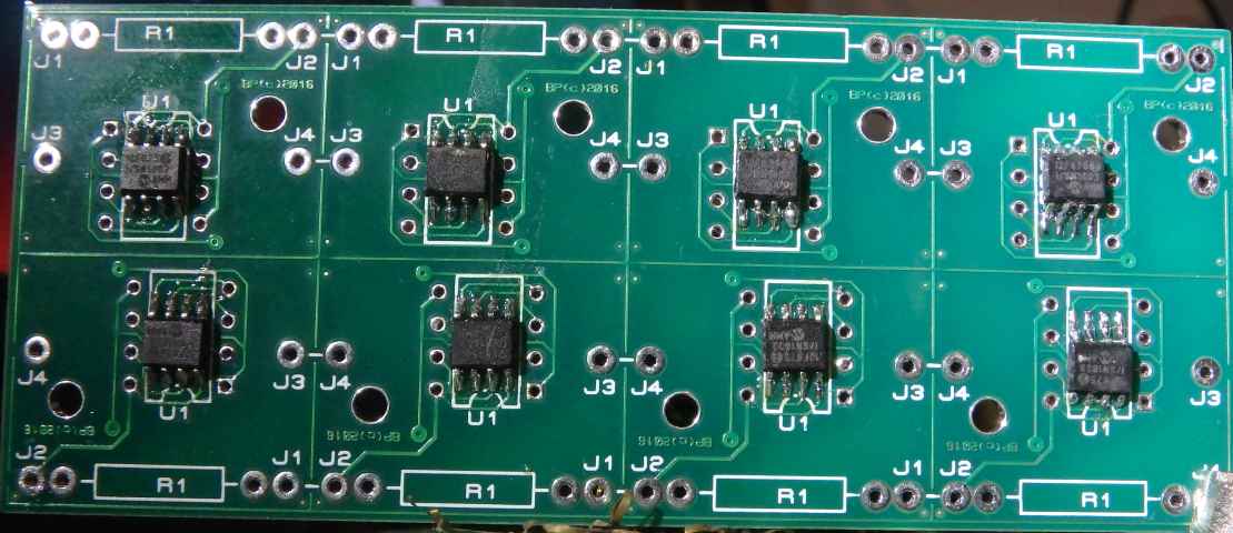
Here's electrical drawing of the cell module:
Where J1 is connected to cell positive, J2 is connected to cell negative pole, J3 is daisy chain input (from previous cell or from central module) and J4 is daisy chain output.
Transistor Q1 is used for bleeding the cell when
it reaches programmable threshold point. Resistor R1 has to be chosen according
to the nominal cell voltage and allowed power dissipation; recommended value is
8.8 Ohms for LiFePO4 cells and 8.2 Ohms for LiPo cells. Large cells need bigger
bleeding current and this cell module can bleed current up to 1A (with R1
resistor on the heat sink). The advantage of bigger bleeding current is that the
balancing process will take less time, but more heat will be dissipated, the
bigger R1 is - less heat will be produced but the balancing will take longer
time.
The light emitting diode D1 with resistor R6 can be omitted as is used only to indicate
bleeding process, which can be indicated on central module too.
The command to the cell module is received through resistor R7 and the cell sends the messages through resistor R4 and transistor Q2 in common base mode, which is used for level shifting.
Note: The first cell in the chain has smaller resistors R7 (75 Ohms) and R8 (470 Ohms) and is connected to central module via optocoupler in such way that the emitter of the optocoupler is connected to J3 and the collector is connected to pin J1.
Major advantage of this cell module is very low
current consumption in standby mode and good accuracy (+/-5mV for LiPo, +/-3mV
for LiFePO4). When it is not polled, the module draws average current
less than
6µA from LiPo cell, which can be
even less than 3µA on LiFePO4 cell. In other words, the cell module draws in
total les than 80mAh per year.
The low power consumption has been achieved by keeping the microcontroller in
sleep mode, leaving running only watchdog timer and enabling interrupt on pin
GP0 (command input). In sleep mode the microcontroller has been waked up every
~2.3 second when it measures the voltage and sends data out if voltage of the
cell is out of limits (Hi/Lo alarm).
Of course, the microcontroller has been waked up when any data comes in through
GP0 port too.
The voltage of the cell
has been measured in such way that the reference voltage of the A/D converter is
the cell and the voltage of the reference voltage has been converted through
10bit A/D input, using oversampling.
The input is sampled 16 times and the result is rounded to 12 bits.
Oversampling is chosen not only for increasing the resolution, it filters the
transients or glitches too.
The cell module sends (when is polled) the digitized value of the reference voltage, which is reciprocal to cell voltage. The central unit has to calculate the cell voltage from this value. The formula is:
Ucell = Uref * 4096 / ADref
Where ADref is digitized
reference voltage (result of A/D conversion).
The calibration constant is Uref*4096 and it is stored in nonvolatile
microcontroller's memory as well as other three values: High Alarm voltage, Low
Alarm voltage and Bleeding Threshold voltage. These parameters of the cell
module can be easily changed with appropriate commands send to the module.
Note: As the reference voltage is 2048mV, it is obvious that default
calibration constant is 0x800000, decimal: 8388608.
It is obvious that increased reference voltage means increased accuracy. The
reference voltage must be less than the minimal cell voltage too.
Assuming minimal cell voltage 2.5V, 2.048V reference voltage gives best
resolution and accuracy...
The central module (when
it is initialized) has to read calibration voltages for all cells in the chain
in order to calculate cell voltages. It is advisable to keep the cell
calibration constants in the central module in order to reduce the communication
with the cells.
The central module doesn't need these constants if it has no display, i.e. if it is
used only for alarming. Without these constants, the central module is still
able to get status of every cell and indicate hi/lo voltage alarms etc. The cell
modules executes bleeding when needed (during charging the battery or during
regenerative braking).
In addition, the cell module checks the cell voltage at least every ~2.3 seconds
(WDT wakeup) and sends the voltage with the status in case of alarm (hi/lo voltage) without
polling. In other words, the cell module sends the status in case of alarm and
when it has not been waked up due communication (which resets the watchdog
timer).
The communication with the cell module is made through daisy chain and the communication protocol is explained here.
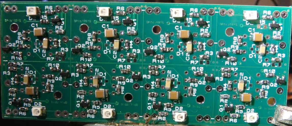
Assembled cell modules: